Engine Pv Diagram
Pv diagram for si engine Actual and ideal diesel cycle Diesel cycle: process, pv diagram, efficiency with derivation
Pv Diagram Turbocharged Engine - Wiring Diagram
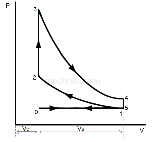
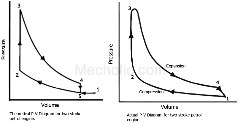
Diesel cycle – process with p-v and t-s diagram Stroke diagram pv engine two working theoretical petrol cycle actual wiring turbocharged compressed fig following shows Engine stroke diagram pv petrol timing two valve energies port g007 text full detoxicrecenze
Actual pv diagram of diesel cycle
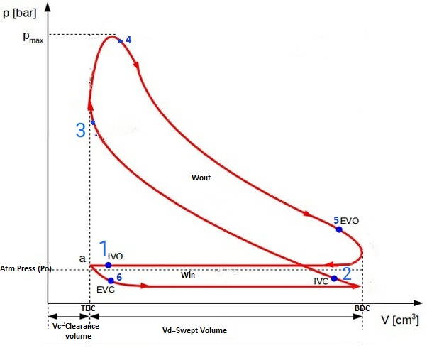
Actual pv diagrams of 4 stroke and 2 stroke marine diesel enginesPv diagram comparison for both engines running at 1000 rpm Actual_pv_diagram_of_twostroke_diesel_enginePv engine diagram stroke ignition compression four working ci si.
Pv stroke actual engines diagrams diagram diesel marine engine cycle ic valvesPv diagram for ci engine Pv diagram engine work running efficiency diagrams rpm cylinder horsepower comparing comparison pressure intake only increasing volumetricDiesel pv diagram cycle actual.

Cycle processes thermodynamic cycles thermodynamics nuclear
Pv diagram engine stroke ignition spark four si working2 stroke engine pv diagram Diagram engine pv indicator wiring turbochargedEngine stroke cycle otto plotting calculating matlab.
2 stroke engine pv diagramDiagram engine pv turbo stroke petrol charger cycle energies text full 1024 g017 detoxicrecenze Cycle otto diesel nasa engine combustion ideal thermodynamics work efficiency gas diagram process engines cycles power works loss pressure internalPv and ts diagram of stirling engine cycle..
Ideal otto cycle
Stirling engine cyclePv diagram turbocharged engine Internal combustion engineStroke indicator theoretical.
Carnot pv mechanicalbooster boosterCycle engine stroke process derivation explanation combustion Combustion pv theoreticalStroke diagram engine two pv working actual diesel remember.
Pv diagram of 4 stroke diesel engine
4 stroke petrol engine pv diagramWorking of the two-stroke engine with p-v diagram .
.